How To Build A Table Saw-Miter Saw Workbench
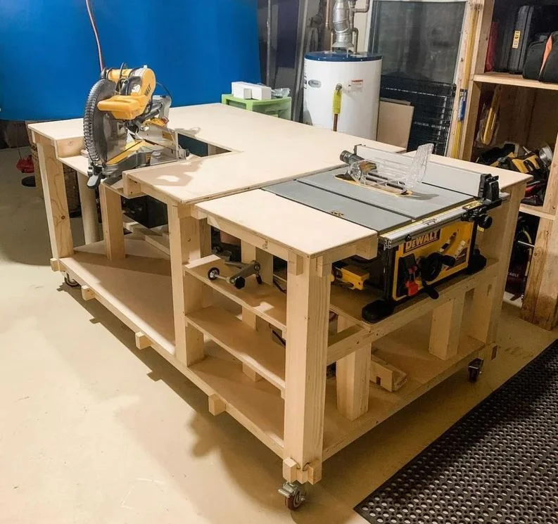
This plan builds (1) Table Saw/ Miter Saw Work bench. Plans are based off of Dewalt DWE-7491 table saw and Dewalt DWS-779 miter saw.
Adjustments to the table’s measurements may need to be made in order to fit your exact saws.
DISCLAIMER: By Downloading these plans you are acknowledging that you claim all responsibility for any injuries, actions or damages that may occur when building or using this project. Learn More
ESTIMATED TOTAL COSTS:
- 2x4’s - $62.80
- 4x4’s - $62.80
- ¾ Plywood Sheets - $106.00
- Hardware - $45.26
Total: $276.85
MATERIALS:
- 2x4x96 = 10
- 4x4x8 = 4
- ¾” Maple Plywood = 2 (4X8’ Sheet)
- 4” Lockable Casters = 4-6
- ½” Aluminum or Steel Rod = 2
- ½” Clamp Collars = 4
TOOLS REQUIRED
Note: As an Amazon Associate, I earn from qualifying purchases.
Work Bench Build - Advanced | The Base
Step 1: Half Lap Frame
The Base will be constructed with a series of half laps and hidden fasteners.
To make the frame you will need the following:
- (X2) Reference Drawing “BASE_2X4_A” *Below in Orange*
- (X5) Reference Drawing “BASE_2X4_B” *Below in Brown*
- (X4) Reference Drawing “BASE_CASTER_SUPPORT” *Below in Red*

TIP: I made my half laps on the table saw using a table saw sled, however a miter saw can be used to make half laps as well.
Using countersunk screws, fasten each half lap where “BASE_2X4_A” and “BASE_2X4_B” meet using 2-1/2” long construction screws.
Fasten the “BASE_CASTER_SUPPORT from the inside to the “BASE_2X4_A”
Reference Drawing: BASE_FRAME_FASTENER ASSEMBLY

Step 2: Castle Joint Legs
Four main legs will support the table top. These legs have castle joints cut on both ends.
For step 2 you will need the following:
(X4) Reference Drawing “BASE_4X4_A” *Below in Dark Brown*

Tip: I made my castle joints on the table saw using a table saw sled, however a skill saw with chisels could also give you the same result.
Step 3: Casters
At this point, this is the best time to install the casters at the bottom of the frame. I used 4” lockable casters from Amazon.
Link for casters: ABSLIMUS 4 inch Heavy Duty Casters
Use 1” Pan-Head Screws to attach the casters. 4 Screws per 1 Caster


TIP:
I used six casters on the base of the work bench for extra support. I work on heavier items and
did not want bowing in the center of the bench.
Step 4: ¾” Plywood Base
Once the casters are secure, flip the bench back over and attach the ¾” plywood bottom. Cut the corners out using a jigsaw so the bottom fits around the legs.
(Reference drawing “3_4_PLY_A” to make this bottom)
(X1) Reference Drawing “BASE_3_4_PLY_A” *Below in Light Orange*

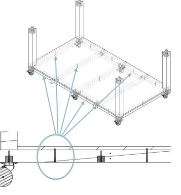
TIP: Secure the plywood from the bottom using (13) 3” long screws. You can choose to use shorter screws and attach them from the top, however this way maintains the look of no fasteners.
Step 5: Inside Leg Posts
Once the plywood base is attached, we will now add three styles of additional legs to support the table top as well as the table saw. Use Reference Drawing “INSIDE_LEG_POSITIONS”
- (X2) Reference Drawing “INSIDE_4X4_B” *Below in Dark Pink*
- (X2) Reference Drawing “INSIDE_4X4_C” *Below in Light Pink*
- (X2) Reference Drawing “INSIDE_4X4_D” *Below in Dark Purple*
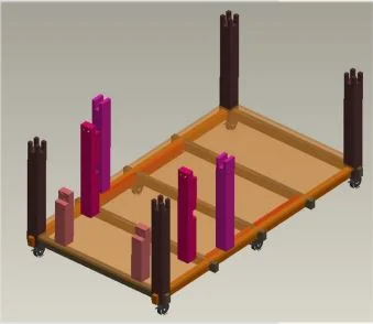
**NOTE: Please read the “Tip” in Step 7 before making any of the inside legs if your saws do not match the equipment this bench was originally intended for.**
TIP: Legs can either be attached by flipping the table on its side and fastening the legs in the correct position from the bottom of the table, or pocket holes can be used.
The legs can be secured with the table right side up and the screws driven through the legs from the side. Both types of fastening methods seen below.

Step 5: Upper Frame
Using the following reference drawings, construct the frame for the top of the work bench. Use Reference Drawing “Upper_Frame” for assembly.
Please note the upper frame may need to be slightly modified for your type of saws. Consult first page of this plan for the types of saws this table was built for.
- (X1) Reference Drawing “TOP_2X4_C” *Below in Burgundy*
- (X2) Reference Drawing “TOP_2X4_D” *Below in Red*
- (X1) Reference Drawing “TOP_2X4_E” *Below in Light Green*
- (X1) Reference Drawing “TOP_2X4_F” *Below in Yellow*
- (X2) Reference Drawing “TOP_2X4_G” *Below in Dark Green*
- (X4) Reference Drawing “TOP_2X4_H” *Below in Orange*
- (X2) Reference Drawing “TOP_2X4_I” *Below in Light Purple*

TIP: Before moving on to attach the ¾” plywood top, screw all the upper framing pieces at each interesting half lap with 2-1/2” screws. At half laps with a post underneath us 3-1/2” screws.
Adjusting for Different Saws: For a wider miter saw, “TOP_2X4_E” and “TOP_2X4_F” Would need to be shortened in length to accept a larger flip tray. For a larger table saw opening, “TOP_2X4_G” and “TOP_2X4_I” would need to be reduced in length.
Step 6: ¾” Plywood Top (3 Pieces)
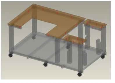
It is now time to attach the plywood top. For mine I used maple ply. This design is in 3 pieces. Use Reference Drawing “TOP_3_4_PLY_B” for dimensions and positioning of the three pieces.

TIP: Secure the plywood from the bottom using (17) 3” long screws, like previously done in Step 4. You can choose to use shorter screws and attach them from the top, however this way maintains the look of no fasteners.
Step 7: Table Saw Landing
The framing for the table saw landing is next. Make one of each piece listed below. Fasten these pieces from the back side so all fasteners are still hidden. Use 2- 1/2 “construction screws to secure the framing.
- (X1) Reference Drawing “LANDING_2X4_J” *Below in Dark Green*
- (X1) Reference Drawing “LANDING_2X4_K” *Below in Light Green*

TIP: My saw (DWE-7491) is 12-3/4” from bottom to top of saw. If your saw “height” varies, you will need to raise/lower this landing so the saws table top sits flush with the work bench’s table top.
To raise and lower the landing, the notch locations in “INSIDE_4X4_B” and “INSIDE_4x4_C” will need to be raised or lowered.
A ¾” plywood landing will sit on top of “LANDING_2X4_J” and “LANDING_2X4_K” So, factor that in when calculating the correct height.
Secure the plywood from the bottom using (6) 3” long screws, like previously done in Step 6. You can choose to use shorter screws and attach them from the top, however this way maintains the look of no fasteners.
- (X1) Reference Drawing “LANDING_3_4_PLY_C” *Below in Blue*

TIP: I used ¾” plywood so my saw sit slightly above the table. This helps make sure the pieces you are running through the saw do not catch. If you want the table saw to sit flush with table top, use a ½” piece of plywood or lower the notches on “INSIDE_4X4_B”and “INSIDE_4x4_C” down 1/4”.
Step 8: Miter Saw Landing
You have made it. The flip top miter saw landing! First start by constructing the base. This consists of three pieces. Use Reference Drawing: MITER_FLIP_ASSEMBLY
- (X2) Reference Drawing “MITER_2X4_L” *Below in Orange*
- (X1) Reference Drawing “MITER_3_4_PLY_D” *Below in Pink*

TIP: Make sure the holes for the pivot are as accurate as possible. Accuracy insures the tray rotates properly and sits in its pocket flush with the table top.
When attaching “MITER_2X4_L” to “MITER_3_4_PLY_D” you can use wood glue and pocket-hole screws to maintain the look of no fasteners. Drill your pocket holes from the outside of the tray into the plywood base.

Once the tray is constructed you will then need to make the two legs that the tray pivots on.
- (X2) Reference Drawing “MITER_4X4_E” *Above in Green*
The legs get assembled onto the tray using the following hardware.
- (X4) McMaster Carr (6157K14) ½” Rod Clamp
- (X2) McMaster Carr (95229A960) Plated Washer
- (X2) McMaster Carr (6750K16) ½” Aluminum Rod 2 pieces, 5-11/16” Long

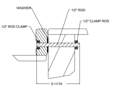

- Assemble the “MITER_4X4_E” legs onto the tray before mounting to the physical bench. It is easy to attach the legs and tighten down the clamps this way.
- Work the tray/leg assembly under the table into place. The front of the tray should match the edge of the workbench. Maintain the gap of the back of the tray outlined in the Reference Drawing: “MITER_FLIP_ASSEMBLY”
- Once the flip top is in place, you can use pocket holes or attach it directly from the table top. I wanted these legs to be as stable as possible, so I did drive screws straight into the table top as shown above and to the left.
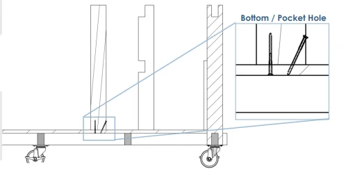
TIP: The bottom of the “MITER_4X4_E” legs can be secured from underneath or using pocket holes like previously illustrated in Step 5.
Step 9: Latches
(4) latches are going to be installed to keep the flip top in place when using or not using the miter saw.
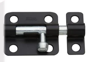
- Using shim and clamps, secure the tray in either the positon it will be in when the miter saw is being used, or the position the tray will be in when the miter saw is flipped down and out of the way.
- Once the tray is secure, attach latches in the four outlined locations, positioning of the latches should be spread out as far as possible to distribute the weight evenly.
- Attach the latches to the underside of the table.
- Once the latches are attached, mark the profile where the strike of the latch comes into contact with the side of “MITER_2X4_L” Each latch will have its own marking.

Drill out holes for the chamfer of the latch to stick into. Make sure the drilled holes are as tight as possible so there is no play in the flip top.

When the four holes are drilled, flip the top around, secure the tray, than drill four new locations for the alternative position the tray can be in.

Step 10: T-Nuts
I used T-Nuts to secure the miter saw into place. My table saw sits in its pocket and I never mount it to the bench.
- (X4) McMaster Carr (90975A332) T- Nuts Because mounting holes on saws are constantly changing, make sure you use your own personal saw as a template to where the T-Nuts to mount the miter saw need to go.
Use “MITER_3_4_PLY_D” As a reference location for the T-Nuts, but note that they may not be the exact location for you

TIP: When installing the T-Nuts, use super glue before banging them into the holes. Let them dry fully before mounting your saw upside down.
The holes that are drilled for the T-Nuts to be hammered into should be tight to the outside diameter of the nut itself.

REFERENCE DRAWING: BASE_2X4_A

REFERENCE DRAWING: BASE_2X4_B

REFERENCE DRAWING: BASE_CASTER_SUPPORT

REFERENCE DRAWING: BASE_FRAME_FASTENER ASSEMBLY

REFERENCE DRAWING: BASE_4X4_A

REFERENCE DRAWING: CASTER ASSEMBLY

REFERENCE DRAWING: BASE_3_4_PLY_A

REFERENCE DRAWING: INSIDE_LEG_POSITIONS

REFERENCE DRAWING: INSIDE_4X4_B

REFERENCE DRAWING: INSIDE_4X4_C

REFERENCE DRAWING: INSIDE_4X4_D

REFERENCE DRAWING: UPPER_FRAME

REFERENCE DRAWING: TOP_2X4_C

REFERENCE DRAWING: TOP_2X4_D
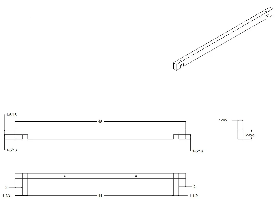
REFERENCE DRAWING: TOP_2X4_E

REFERENCE DRAWING: TOP_2X4_F

REFERENCE DRAWING: TOP_2X4_G

DRAWING REFERENCE: TOP_2X4_H
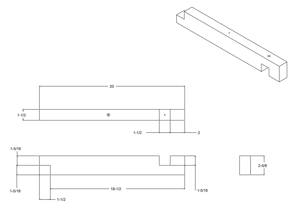
REFERENCE DRAWING: TOP_2X4_I

REFERENCE DRAWING: TOP_3_4_PLY_B

REFERENCE DRAWING: LANDING_2X4_J

REFERNECE DRAWING: LANDING_2X4_K

REFERENCE DRAWING: LANDING_3_4_PLY_C

REFERENCE DRAWING: MITER_FLIP_ASSEMBLY

REFERENCE DRAWING: MITER_2X4_L

REFERENCE DRAWING: MITER_3_4_PLY_D

REFERENCE DRAWING: MITER_4X4_E


You can find this part at https://www.mcmaster.com
Part Number 6157K14 (Clamping Shaft Collar)

You can find this part at https://www.mcmaster.com
Part Number 95229A960 (Cadmium-Plated Steel MIL. Spec. Washer)

You can find this part at https://www.mcmaster.com
Part Number 6750K161 (Anodized Multipurpose 6061 Aluminum Rod)

You can find this part at https://www.mcmaster.com
Part Number 90975A332 (Steel Tee Nut Inserts)

